
Precision converting for robotics & UAV programs
IATF 16949ISO 9001ISO 14001
Engineering support

Turn an interface problem into a manufacturable part

We help engineering teams define material, adhesive, liner, lamination and die-cut geometry around the complete assembly—then support fit checks and prototype evaluation before scale-up.
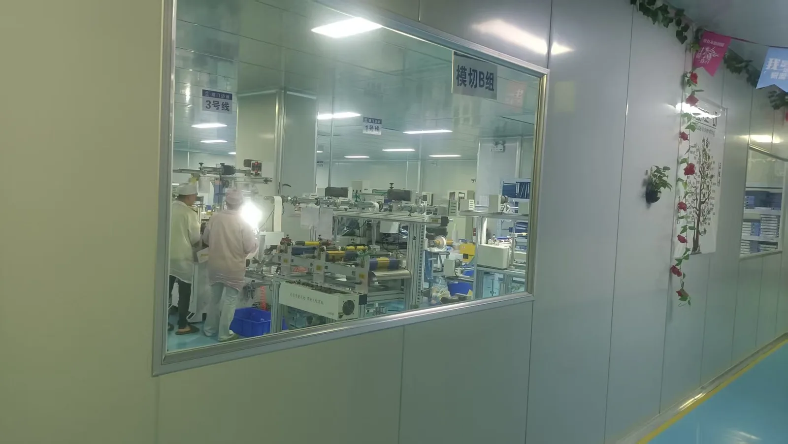
View from the factory corridor into a clean converting workshop

Tolerances are reviewed against material, thickness, geometry and laminated construction rather than stated as one universal value.

Engineering workflow

Four decisions between a problem and a production part

  1. 01 / INPUT

    Define the position

    Assembly drawing, substrate, interface gap, compression, temperature and functional target.

  2. 02 / CONSTRUCTION

    Choose the stack

    Base material, adhesive system, carrier, protective layer, liner and assembly features.

  3. 03 / PROTOTYPE

    Validate in context

    Fit, handling and application-specific performance in the customer’s complete assembly.

  4. 04 / INDUSTRIALIZE

    Plan for repeatability

    Tooling, process route, inspection points, delivery format and volume transition.

Engineering review framework

From project inputs to a defined component specification

Each review connects functional targets and assembly conditions to a proposed construction, supporting data and an agreed validation plan.

Data familyProject inputsFLEXCEND deliverables
Geometry & assemblyDrawing, gap, CTQs, tolerance stack, installation methodDFM review, converted stack, tooling route, critical-dimension plan
ThermalHeat source, power, interfaces, temperature targetGrade data, thickness, thermal path, samples for assembly validation
EMI / groundingFrequency, ground path, seam, compressionResistance, shielding test basis, gasket or tape construction
Compression / vibrationMass, gap, strain, force limit, spectrumMaterial curve, compression window, prototype comparison set
Electrical insulationVoltage, temperature, clearance, flame needFilm grade, thickness, dielectric and compliance documentation
Dust / water / acousticOpening, airflow, pressure, exposure, acoustic targetMesh or membrane, adhesive frame, grade data and validation plan
Adhesive & surfaceSubstrate, surface energy, dwell, temperature, fluidsAdhesive system, bond area, liner, tab and application method
Quality & supplyVolume, revision, inspection, packing, traceabilityControl points, project data package, delivery format and scale-up plan
Decision matrix

Start with function, then narrow the material family

NeedCommon candidateCritical inputs
Spread concentrated heatGraphite heat spreaderHeat map, thickness, spread area, isolation
Bridge a thermal gapThermal silicone padGap, pressure, flatness, temperature
Create conductive contactFabric tape / conductive foamFrequency, ground path, compression
Control motion or rattleFoam / silicone cushioningMass, gap, compression, recovery
Isolate electricallyPET / PI filmVoltage, temperature, geometry, thickness
Control dust / pressureMesh / vent membraneOpening, airflow, exposure, bond surface
Representative ranges

Numeric windows for early engineering screening

These ranges help an engineering team decide whether a material family deserves a detailed review. The exact grade and finished part remain drawing-controlled.

Component familyRepresentative valuesImportant boundary
Thermal graphite0.070–0.100 mm; 700–1,000 W/m·K in-planeGraphite is conductive; lamination changes the stack limit
Thermal silicone pad0.50–3.18 mm; 1.0–10.0 W/m·KGap, pressure and contact condition drive the result
Conductive fabric / foam0.030–5.00 mm; about 50–95 dB reference dataFrequency, grounding and installed compression govern system EMI
Cushioning foam0.53–25.40 mm; about 1.7–310 kPa CFD across familiesNever compare values without strain and test method
PET / PI insulation0.012–0.500 mm; about 154–350 kV/mm selected filmsVoltage, edges, creepage and adhesive stack require review
Vent membrane100–270 mL/min at 70 mbar; >0.6 bar WEP referenceIP rating belongs to the validated installed enclosure

Evidence boundary: Published ranges are representative design-screening windows across material families FLEXCEND can source, convert and evaluate. They are not one universal finished-part specification. Final values are confirmed against the exact grade, thickness, adhesive stack, test method, approved drawing, production lot and complete customer assembly.

Engineering review

Put your drawing in front of a converting engineer

Tell us the installation position, material challenge, environment and project stage. Our team will review the drawing and recommend a practical construction.

Prefer a full brief? Open the detailed RFQ.