
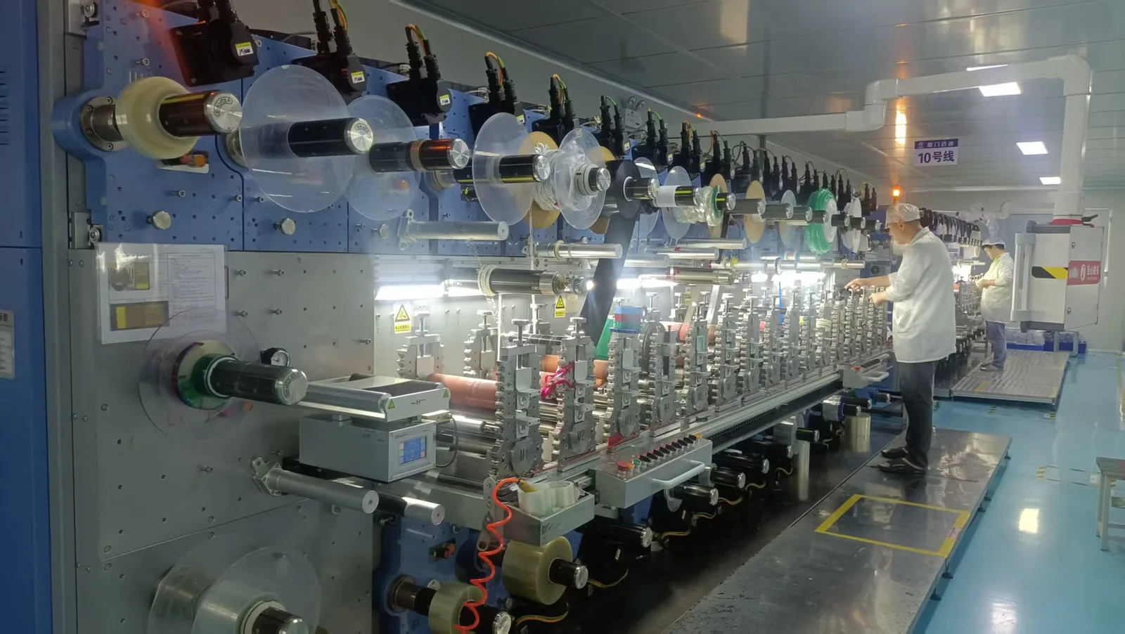
Reliable robotic removal of die-cut adhesive liners depends on three drawing-level decisions: liner release force, pull tab geometry, and presentation format. Specify these before tooling, and validate them with the actual robot, gripper, and liner material.
Why Liner Removal Fails in Robotic Cells
A robot removes a liner by gripping the pull tab and peeling it away. Failure occurs when the tab is too small to grasp, the liner release force exceeds the gripper's holding force, or the part moves during peeling. These failures are design problems, not robot programming problems.
Robotic tape application systems combine handling, inspection, and assembly, but they assume the incoming part is presented consistently. If the liner varies in release force or tab position, the robot cannot compensate reliably.[1]
- Gripper cannot find or hold the tab
- Liner tears or leaves adhesive residue
- Part lifts with the liner
- Tab folds over or sticks to the liner
Specifying Liner Release Force
Liner release force is the peel force required to separate the liner from the adhesive at a specified angle and speed. It is not a single material property; it depends on the adhesive, liner surface energy, dwell time, temperature, and peel geometry. Specify a target range and test method on the drawing.
For robotic removal, a common screening range is 0.5 to 5 N per 25 mm width at 180° peel and 300 mm/min, but this is only a starting point. The robot's gripper force, acceleration, and peel angle determine the acceptable upper limit. Validate with the actual liner and adhesive stack.
- State peel angle (90° or 180°) and speed
- Define width and test specimen
- Set upper and lower limits, not a single value
- Include dwell time and temperature conditioning
Pull Tab Geometry for Reliable Grasping
The pull tab must be large enough for the gripper to locate and hold without touching the adhesive. A tab length of at least 5 mm beyond the part edge is typical, but the robot's vision and gripper tolerance dictate the minimum. The tab should be on a corner or straight edge, not in a recess.
Kiss cutting creates a tab by cutting through the adhesive and liner but not the carrier, leaving the part attached to a continuous liner. Through cutting separates the part and liner completely, requiring a separate tab or extended liner. Choose based on presentation format.[2]
- Tab length ≥ 5 mm beyond part edge
- Tab width ≥ 3 mm for vacuum or mechanical grip
- Avoid tabs that fold or curl
- Specify tab location relative to part datum
Kiss Cut vs Through Cut for Robotic Handling
Kiss cutting leaves the part on a continuous liner, which can be wound on a roll or presented in a tray. The robot peels the part from the liner, but the liner remains as waste. Through cutting separates each part with its own liner, allowing individual presentation but requiring liner removal as a separate step.[2]
For robotic pick-and-place, kiss-cut parts on a roll are common because the liner provides a consistent presentation surface. However, the robot must peel the part without disturbing adjacent parts. Through-cut parts in a tray or tape-and-reel allow individual grasping but add liner removal complexity.
- Kiss cut: continuous liner, roll or sheet presentation
- Through cut: individual parts, tray or tape presentation
- Consider liner waste removal in the cell
- Match cut type to robot end-effector
Presentation Format and Liner Orientation
The presentation format determines how the robot sees and grasps the part. Common formats include rolls, sheets, trays, and tape-and-reel. Each format affects liner orientation, tab accessibility, and the need for vision guidance. Specify the format on the drawing and validate it with the robot.
Vision-guided pick-and-place can locate parts in trays or on conveyors, but it requires stable features. The liner tab must be visually distinct from the part and background. Reflective or transparent liners can challenge vision systems, so test with the actual lighting and camera.[3]
- Roll: continuous liner, high density, needs peeling station
- Sheet: flat presentation, easy vision, manual or robotic loading
- Tray: individual pockets, stable orientation, higher cost
- Tape-and-reel: for small parts, automated feeding
Validation Protocol for Liner Removal
Before releasing the part drawing, run a validation protocol in the robotic cell. Use the actual liner material, adhesive, and part geometry. Measure release force at the robot's peel speed and angle. Confirm the gripper can hold the tab without slipping or damaging the part.
A practical protocol includes: 1) measure liner release force on a tensile tester at the robot's peel angle and speed; 2) verify tab grasp with the robot's gripper for 100 cycles; 3) check for adhesive transfer or liner tearing; 4) confirm part remains in place during peeling; 5) document all parameters.
- Measure release force at robot peel speed
- Run 100-cycle grasp test
- Inspect for adhesive transfer
- Record all parameters for future lots
Drawing Inputs for a FLEXCEND Review
A complete drawing for a die-cut adhesive part with liner should include: part geometry and tolerances, adhesive and liner material specifications, kiss cut or through cut, pull tab dimensions and location, liner release force range and test method, presentation format, and any cleanliness or contamination requirements.
FLEXCEND can review the drawing for manufacturability and suggest adjustments to improve robotic handling. Provide the robot's gripper type, peel speed, and vision constraints to enable a focused review.
- Part geometry and tolerances
- Adhesive and liner material specs
- Cut type and tab dimensions
- Release force range and test method
- Presentation format and quantity
What to send for a useful review
- Part drawing with dimensions and tolerances
- Adhesive and liner material specifications
- Kiss cut or through cut requirement
- Pull tab length, width, and location
- Liner release force target range and test method
- Presentation format (roll, sheet, tray, tape-and-reel)
- Robot gripper type and peel speed
- Vision system constraints (lighting, contrast)
- Expected annual volume and lot size
- Any cleanliness or contamination requirements
Questions teams ask during selection
What liner release force is typical for robotic removal?
A common screening range is 0.5 to 5 N per 25 mm width at 180° peel and 300 mm/min, but the robot's gripper force and peel speed determine the acceptable upper limit. Validate with the actual adhesive and liner.
How large should the pull tab be?
A tab length of at least 5 mm beyond the part edge and a width of at least 3 mm are typical starting points, but the robot's vision and gripper tolerance dictate the minimum. Test with the actual end-effector.
Should I use kiss cut or through cut for robotic assembly?
Kiss cut leaves parts on a continuous liner, suitable for roll or sheet presentation. Through cut separates each part with its own liner, requiring individual handling. Choose based on presentation format and liner waste removal.[2]
How do I prevent the part from lifting with the liner?
Ensure the liner release force is below the adhesive's bond to the part, and specify a peel angle that separates the liner without stressing the part. A vacuum or mechanical hold-down may be needed during peeling.
What presentation format works best for vision-guided robots?
Trays or sheets with stable, high-contrast features are easiest for vision. Rolls require a peeling station and may need additional sensing. Test with the actual lighting and camera.[3]
Sources and technical references
References support the published context and cited data. Final material and assembly decisions still require grade-specific documentation and application validation.
- Industrial Robotics & Tape Application Automation | Straubstraubdesign.com · Accessed
- Die Cutting Services: Rotary & Flat Bed Solutionscgstape.com · Published · Accessed
- Vision-Guided Pick and Place Robotics Explainedultralytics.com · Published · Accessed