
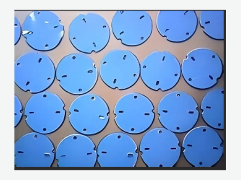
A thermal pad in a compact ESC is part of an interface, not an isolated material. The useful specification connects the selected grade and die-cut geometry to the real gap, contact surfaces, mounting force and electrical requirements.
Begin with the complete heat path
Identify the heat-generating components, the intended heat sink or housing surface, and every layer between them. A high material conductivity does not compensate for a poorly defined contact area, excessive thickness or incomplete surface contact.
Mark the interface directly on the assembly drawing. Include nearby components, openings and keep-out zones so the pad outline can support heat transfer without interfering with connectors or fasteners.
- Heat source and estimated load
- Target housing or heat-spreading surface
- Available contact area
- Electrical isolation requirement
Define nominal gap and tolerance stack
The nominal gap alone is not enough. Housing flatness, PCB position, component height and assembly variation determine the minimum and maximum installed gap. These values guide pad thickness and the intended compression window.
The drawing should also state whether the pad must bridge several components of different heights or one controlled interface. That decision can change the construction and part geometry.
- Minimum, nominal and maximum gap
- Component and housing tolerances
- Permitted pressure on the PCB and devices
- Fastener position and assembly sequence
Compare materials under installed conditions
Review conductivity together with thickness, hardness, compression force, thermal resistance and temperature limits. Where available, use grade-specific curves and test conditions rather than comparing unrelated headline values.
If dielectric performance or flame documentation is required, connect that requirement to the exact selected grade and full laminated construction. Do not assume that every grade in a product family carries the same evidence.
Prototype the interface, not only the outline
A fit sample can confirm outline, liner handling and assembly access. Thermal and mechanical validation should then be completed in the intended ESC and enclosure under relevant power, mounting and environmental conditions.
The released drawing can record material grade, thickness, adhesive or natural-tack surface, liner, orientation, critical dimensions and agreed inspection points.
What to send for a useful review
- ESC and enclosure drawing
- Gap and tolerance stack
- Heat source and temperature target
- Mounting pressure or force limit
- Isolation and compliance needs
- Prototype and annual volume