Precision converting for robotics & UAV programs
IATF 16949ISO 9001ISO 14001
Custom product

Custom Battery Compression & Cushioning Pads

Die-cut foam and silicone pad constructions for spacing, cushioning and controlled contact within customer-designed UAV and mobile-robot battery assemblies.

Custom die-cutMulti-layer laminationPrototype supportDocumented inspection
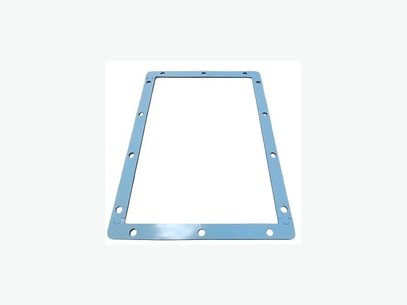
Battery Compression Pads sample
Representative converted component. Final construction is made to drawing.
Function

What this component solves

Accommodates selected cell-to-housing or pack-interface variation while supporting controlled compression and repeatable placement.

Typical install positions

  • Cell-to-housing interface
  • Pack lid
  • Cell spacer location
  • Battery bay support
  • Module edge or end plate
Engineering selection

Data your engineering team can specify

We define the finished part around the selected material grade, test basis, drawing and assembly conditions. The items below can be included in the project review and data package.

Typical screening rangeCustomizable by FLEXCENDGrade-specific data availableAssembly validation required
Data pointWhat FLEXCEND can define or provide
ThicknessRepresentative EV-pad range: 1.0–3.0 mm; broader foam constructions up to about 6.35 mm can be reviewed
DensityRepresentative battery-pad material family: 112–400 kg/m³
Stress at 25% deflectionRepresentative selected EV-pad grades: 10.3–83 kPa under ASTM D3574 conditions
Design compression windowStress-strain data can be evaluated from 10–70% strain; the approved operating window follows cell swelling and pack force limits
Compression setSelected EV-pad grades publish ≤5% at 70°C under ASTM D3574; exact construction and aging plan must match the pack
Temperature referenceRepresentative polyurethane family: 90°C recommended constant use and 121°C intermittent; complete pack validation remains required
Stress-strain / pressure curveCandidate material force can be compared across the required compression window
Compression set and creepLong-term recovery reviewed against temperature, time, cycling and pack duty
Thickness and toleranceNominal thickness selected from the cell, housing and swelling tolerance stack
Temperature and agingContinuous, peak and environmental aging limits matched to the selected construction
Electrical / thermal behaviorDielectric and thermal data supplied when relevant to the selected material grade
Flammability and complianceUL 94, RoHS, REACH or halogen documentation tied to the exact selected material

How to read these values: Published ranges are representative design-screening windows across material families FLEXCEND can source, convert and evaluate. They are not one universal finished-part specification. Final values are confirmed against the exact grade, thickness, adhesive stack, test method, approved drawing, production lot and complete customer assembly.

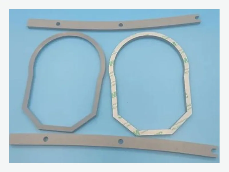
Battery Compression Pads material and die-cut geometry detail
Representative sample

See the material and converted geometry.

This image was extracted from the supplied product library and shows a representative part family. Exact material, grade, thickness and dimensions are defined by the approved drawing and material specification.

Engineering evidence

A project data package—not a generic material claim.

The exact content is agreed by program. Performance values stay linked to the selected material, thickness, method and test condition.

01

Material definition

Approved material grade, complete layer stack, adhesive, carrier and liner recorded against the customer drawing

02

Performance evidence

Supplier TDS or relevant test data tied to the selected grade, thickness, method and test condition

03

Dimensional control

Critical dimensions and tolerances reviewed against material behavior, part geometry, tooling and process route

04

Prototype / first article

Fit samples, comparison sets and dimensional reporting can be agreed before production release

05

Compliance documents

RoHS, REACH, halogen, flammability or other declarations supplied only when supported by the exact selected material

06

Traceability and delivery

Drawing revision, material or production lot, inspection plan, liner format, kitting and packaging defined by program

Made to drawing

Configure the complete part—not just the base material.

We review how material, adhesive, liner, lamination, geometry and delivery format work together at assembly.

  • Custom thickness and outline
  • Pressure-sensitive adhesive
  • Film carrier or insulation layer
  • Adhesive-free zones
  • Cell or housing registration features
  • Prototype and production formats
Fast technical response

Send the inputs engineers use to make a real selection

A drawing plus these operating conditions lets us recommend a practical construction instead of a generic material.

  • Cell format and chemistry
  • Nominal gap, tolerances and swelling allowance
  • Target pressure or compression window
  • Temperature and expected service life
  • Electrical, thermal and flame requirements
  • Pack drawing, prototype plan and annual volume
Engineering boundary

These are converted components for packs designed by the customer. Cell restraint, pack safety and long-term compression require system-level engineering and validation.

Application fit

Where this product is commonly considered

application

UAV Battery Protection

Custom lightweight spacing, cushioning, insulation and thermal-interface parts for UAV battery packs designed by the customer’s battery engineering team.

Explore
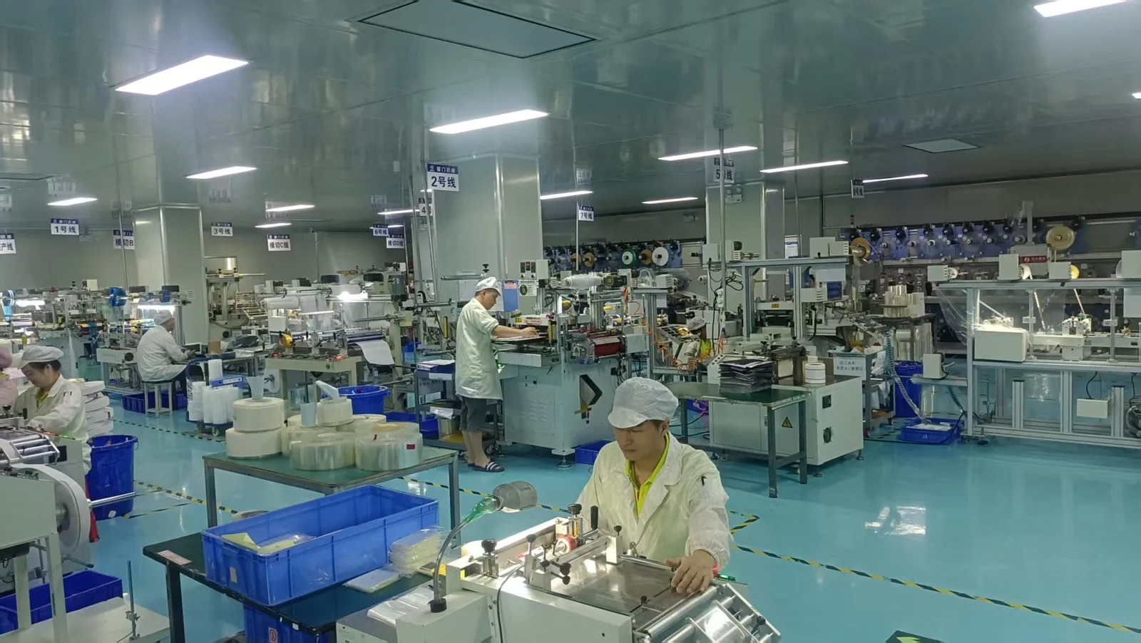
Production team working across multiple die-cutting lines
Manufacturing path

Slit, laminate, die-cut and inspect.

Prototype and production methods are selected around the material behavior, geometry, laminated stack and program volume.

See factory capabilities
Engineering review

Request a custom battery compression pads review

Tell us the installation position, material challenge, environment and project stage. Our team will review the drawing and recommend a practical construction.

Prefer a full brief? Open the detailed RFQ.