
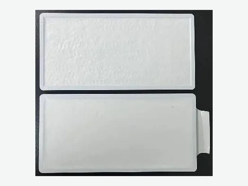
Specifying a compression pad for a UAV pouch cell pack is a tolerance and force-control problem before it is a material selection problem. The pad must maintain a defined pressure window as cells swell, temperature changes, and the pack ages. Start by defining that window and the acceptable compression set, then compare pad materials against those numbers.
Why UAV Pouch Cells Need Controlled Compression
Pouch cells in UAV packs expand and contract with state of charge, temperature, and aging. Without a compliant interface, the pack housing either over-constrains the cells or leaves them loose. Over-constraint increases local pressure and can accelerate lithium plating or separator damage. Under-constraint allows delamination and increases internal resistance. A compression pad converts the fixed housing gap into a controlled force range.
Uniform pressure across the cell face is critical. Non-uniform loading creates current density gradients and uneven aging. A pad with a flat stress-strain curve over the expected swelling range keeps pressure more consistent than a stiff spring or rigid shim.[1]
- Cell swelling allowance typically drives the pad thickness and compression range.
- Pressure uniformity matters as much as average pressure for cycle life.
- The pad must work across the full state-of-charge and temperature envelope.
Define the Pressure Window Before Comparing Materials
The first specification input is the target pressure on the cell face. For many pouch cells, a representative design window is 30–100 kPa, but the exact range depends on cell chemistry, format, and manufacturer data. Some cell suppliers recommend higher pressures for silicon-dominant anodes. The pad must stay within that window from initial assembly through end-of-life swelling.
A common mistake is to specify only the initial compression force. The pad loses force over time through compression set and stress relaxation. If the initial force is at the bottom of the window, the aged force will fall below it. Specify the minimum force after aging, not just at assembly.[2]
- Target pressure window: e.g., 30–100 kPa on the cell face.
- Include end-of-life swelling in the compression range.
- Specify minimum force after aging, not just initial force.
Compression Set and Creep: The Long-Term Specification
Compression set measures how much thickness a pad loses after being held compressed at temperature. For UAV packs that see 50–70°C near the cells, a pad with high compression set will lose force within months. Selected polyurethane battery pad grades publish compression set of 5% or less at 70°C under ASTM D3574, but that is a material coupon value. The installed pad also sees shear, vibration, and thermal cycling, so the pack-level force retention must be validated.[3]
Creep is the time-dependent deformation under constant load. A pad can pass a short compression set test but still creep significantly over 500 cycles. For UAV packs with frequent charge-discharge cycles, request creep data at the maximum operating temperature and the expected compression strain.
- Compression set: ≤5% at 70°C is a useful screening target for polyurethane pads.
- Creep data at max temperature and strain is more relevant than room-temperature data.
- Validate force retention in the assembled pack, not just on a material coupon.
Tolerance Stack: Pad Thickness, Cell Swelling, and Housing Gap
The pad thickness is not a free variable. It fills the difference between the housing gap and the cell stack height, including all tolerances and the expected swelling. A representative battery pad family is available from 1.0–3.0 mm, with broader foam constructions up to about 6.35 mm. The selected thickness must keep the pad within its design compression window at both minimum and maximum stack conditions.[3]
Build the tolerance stack from cell thickness tolerance, cell swelling allowance, housing machining tolerance, and pad thickness tolerance. If the pad is too thin, it bottoms out at high swelling. If too thick, it may exceed the housing gap at minimum stack. A pad with a wide usable compression range, such as 10–70% strain for screening, gives more design margin.[3]
- Pad thickness = housing gap − cell stack height − swelling allowance.
- Include all tolerances: cell, housing, pad, and assembly.
- Choose a pad with a wide usable compression range for robustness.
Electrical Isolation and Thermal Propagation in UAV Packs
UAV packs are weight-sensitive, so every layer must earn its mass. A compression pad can also provide electrical isolation between the cell and housing if the material has sufficient dielectric strength. Specify the required withstand voltage and test method, and confirm the pad's dielectric performance at the maximum compression and temperature.
Thermal propagation is a separate function. Aerogel thermal barriers add a low-profile thermal resistance layer between cells or between cells and housing. Representative aerogel core thermal conductivity is about 0.012–0.030 W/m·K near room temperature, but the complete barrier stack with facings and encapsulation must be validated under the intended compression and temperature. A compression pad is not a thermal barrier, and an aerogel barrier is not a compression pad. Some packs use both in different locations.[4]
- Specify dielectric withstand voltage for the pad if it contacts live cell tabs.
- Aerogel barriers add thermal resistance but do not replace compression pads.
- Weight budget drives material choice in UAV packs.
Validation Protocol for UAV Compression Pads
A practical validation sequence starts with material-level screening, then moves to pack-level testing. First, measure the pad's stress-strain curve at 25°C, 45°C, and 70°C. Confirm the force at minimum and maximum compression falls within the target window. Then run compression set per ASTM D3574 at the maximum pack temperature. Finally, cycle a representative pack with the pad installed and measure cell face pressure at beginning and end of life.[3]
The decision matrix below summarizes the key parameters and how to compare candidate pads. Use it during drawing review to ensure the specification is complete.
- Material screening: stress-strain at 25°C, 45°C, 70°C.
- Compression set per ASTM D3574 at max temperature.
- Pack-level cycling with pressure mapping or force sensors.
Compression Pad Decision Matrix
Use this matrix to compare candidate pads against your defined requirements. Each row is a specification input that should appear on the drawing or RFQ.
- Target pressure window (kPa): minimum and maximum on cell face.
- Compression range (% strain): from initial assembly to end-of-life swelling.
- Compression set (%): maximum allowed at pack temperature and time.
- Thickness tolerance (mm): from pad drawing and tolerance stack.
- Dielectric strength (kV/mm or withstand voltage): if electrical isolation is required.
- Temperature range (°C): continuous and peak operating limits.
- Flammability rating: UL 94 or equivalent for the selected material.
- Weight (g per pad): critical for UAV mass budget.
What to send for a useful review
- Cell format, chemistry, and manufacturer's recommended pressure range.
- Nominal housing gap, cell stack height, and all tolerances.
- Expected cell swelling from 0% to 100% state of charge and end-of-life.
- Target pressure window on the cell face (kPa).
- Maximum allowed compression set at pack operating temperature.
- Required dielectric withstand voltage if the pad contacts live parts.
- Continuous and peak operating temperature for the pad location.
- Flammability rating and any regulatory requirements (UL 94, RoHS, REACH).
- Pad drawing with thickness, tolerance, and any adhesive or PSA requirement.
- Prototype plan and annual volume for pad production.
Questions teams ask during selection
What compression pressure range is typical for UAV pouch cells?
A representative design window is 30–100 kPa on the cell face, but the exact range depends on cell chemistry and manufacturer data. Some silicon-dominant anodes require higher pressure. Always confirm with the cell supplier.
How much compression set is acceptable for a UAV battery pad?
Selected polyurethane battery pad grades publish compression set of 5% or less at 70°C under ASTM D3574. However, the installed pad also sees shear and thermal cycling, so pack-level force retention must be validated.[3]
Can a compression pad also act as a thermal barrier?
No. Compression pads provide controlled force and may offer electrical isolation, but they are not thermal barriers. Aerogel thermal barriers add thermal resistance but do not replace compression pads. Some packs use both in different locations.[4]
What thickness tolerance should I specify for a compression pad?
Thickness tolerance depends on the pad material and converting process. A representative battery pad family is available from 1.0–3.0 mm, with broader foam constructions up to about 6.35 mm. The tolerance must be included in the pack tolerance stack.[3]
How do I validate compression pad performance in a UAV pack?
Start with material stress-strain curves at 25°C, 45°C, and 70°C. Run compression set per ASTM D3574 at the maximum pack temperature. Then cycle a representative pack with the pad installed and measure cell face pressure at beginning and end of life.[3]
Sources and technical references
References support the published context and cited data. Final material and assembly decisions still require grade-specific documentation and application validation.
- Why Uniform Pressure is Crucial in Pouch Cell Testingwattcrafts.com · Accessed
- The Role of Compression Pads in EV Batteriesazom.com · Published · Accessed
- Battery Compression Pads engineering data and screening boundariesFLEXCEND Engineering · Accessed
- Aerogel Thermal Barriers engineering data and screening boundariesFLEXCEND Engineering · Accessed