
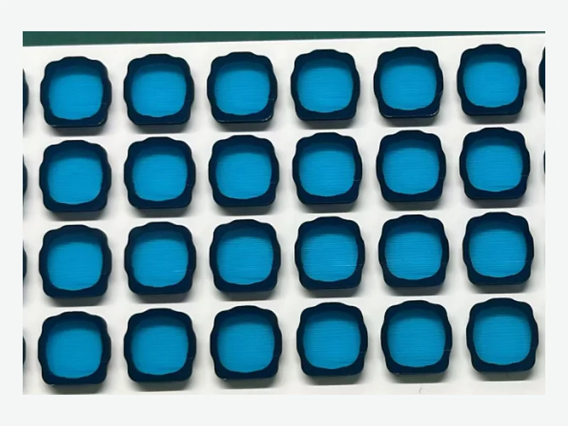
Specify compression set for a drone camera vibration foam by defining the installed compression, the temperature range the module will see, and the minimum recovery needed to hold optical alignment. A low compression set value alone is not enough; the test conditions and the foam's behavior at the actual strain and temperature matter more than a single percentage.
Why compression set drives camera alignment drift
A drone camera isolation foam is compressed between the camera module and the gimbal or airframe. If the foam takes a permanent set, its thickness decreases, the preload drops, and the camera can shift or tilt under vibration. Alignment drift is often traced to foam that was specified only by density or feel, without a compression set requirement tied to the installed strain and temperature.
Compression set is the percentage of original thickness that does not recover after a defined compression and temperature cycle. For a camera foam, the relevant test should mimic the installed compression, not an arbitrary 25% or 50% deflection. A foam that shows 5% set at 25% deflection may show much higher set at 40% deflection or at elevated temperature.[1]
- Define installed compression as a percentage of free thickness, typically 10–30% for isolation foams.
- Specify compression set after 22–70 hours at the maximum service temperature, per ASTM D3574 or D1056.
- Require recovery measurement after a defined rest period, not just immediate thickness.
Installed compression: the missing specification input
Installed compression is the ratio of the foam's compressed thickness to its free thickness. It sets the preload and the natural frequency of the isolation system. Too little compression leaves the camera loose; too much accelerates set and can bottom out the foam. For a drone camera, a common starting range is 10–30% compression, but the exact value depends on the supported mass, vibration spectrum, and available gap.
The compression force-deflection curve at the intended strain tells you the preload. For example, a representative PU foam family shows about 1.7–55 kPa at 25% deflection, while silicone constructions can range from 20–310 kPa at their published strain. These are screening ranges; the exact grade and test method control the released value.[2] [3]
- Calculate installed compression from the nominal gap and foam free thickness.
- Check the force at that compression against the camera's allowable preload.
- Keep the compression below the foam's stress-relaxation knee to limit set.
Material comparison: silicone vs. PU vs. EVA for low set
Silicone foam generally offers the lowest compression set and the widest temperature range. Selected silicone grades can cover approximately -51 to 204°C, and published compression set values are often under 5% under stated conditions. PU foam, such as PORON, can also achieve low set, typically under 10% per ASTM D3574, but its temperature range is narrower. EVA foam is less resilient and more prone to set at elevated temperature, so it is usually reserved for low-cost, low-duty applications.[1] [2] [3]
The choice is not purely about set. Silicone foam costs more and may have higher outgassing or adhesive compatibility issues. PU foam offers better dynamic cycling and lower cost. EVA is closed-cell and can provide some sealing, but its recovery is poorer. For a drone camera that must hold alignment over years, silicone or a low-set PU is usually the safer starting point.[1]
- Silicone foam: lowest set, widest temperature, higher cost.
- PU foam: good set, excellent dynamic cycling, moderate temperature.
- EVA foam: low cost, closed-cell, but higher set and temperature sensitivity.
Specifying compression set on the drawing
A drawing note such as 'Compression set ≤ 10% per ASTM D3574, 25% deflection, 70 h at 70°C' is a start, but it may not reflect the installed condition. Better practice is to specify the test at the installed compression and the maximum service temperature, and to require a recovery measurement after 30 minutes or 24 hours. For example: 'Compression set ≤ 8% after 22 h at 85°C, 30% deflection; recovery ≥ 95% after 24 h at 23°C.'
The drawing should also call out the foam family, thickness tolerance, and any adhesive or liner. FLEXCEND can review the drawing against available grades and advise on realistic set values for the chosen material and geometry. The final specification must be validated on production parts, not just datasheet values.[2]
- State compression set test method, deflection, time, and temperature.
- Add a recovery requirement after a defined rest period.
- Include foam family, thickness, and adhesive stack on the drawing.
Validation protocol for camera foam recovery
Before releasing the design, run a simple bench test: compress the foam to the installed thickness between two flat plates, hold at the maximum service temperature for 22–70 hours, release, and measure thickness after 30 minutes and 24 hours. The recovered thickness should be at least 95% of the original for alignment stability. Then repeat the test with the actual camera mass and vibration profile to confirm no drift.
A more complete protocol includes thermal cycling, humidity, and repeated compression cycles. For a drone camera, also test at low temperature, because some foams stiffen and lose recovery below 0°C. Silicone foam maintains resilience down to about -51°C, while PU and EVA may harden.[1] [2]
- Bench compression set test at installed strain and max temperature.
- Recovery measurement after 30 min and 24 h.
- Assembly-level vibration test with camera mass to check alignment drift.
Decision matrix for foam selection
Use the following matrix to shortlist materials. Score each candidate from 1 (poor) to 5 (excellent) for compression set, temperature range, dynamic cycling, cost, and availability. Weight the scores by your application: for a drone camera, compression set and temperature range usually dominate.
- Silicone foam: set 5, temperature 5, cycling 4, cost 2, availability 4.
- PU foam (low-set grade): set 4, temperature 3, cycling 5, cost 4, availability 5.
- EVA foam: set 2, temperature 2, cycling 3, cost 5, availability 5.
Common specification mistakes
One mistake is specifying compression set without stating the test temperature. A foam that passes at 23°C may fail at 70°C. Another is ignoring recovery time; immediate thickness after release is not the same as long-term recovery. Finally, specifying a set value that is impossible for the chosen material family leads to unnecessary cost or supplier nonconformance.
- Always state test temperature and duration.
- Require recovery after a defined rest period.
- Check feasibility of the set value with the material supplier before finalizing the drawing.
What to send for a useful review
- Supported camera module mass and center of gravity
- Vibration spectrum or shock condition from the drone platform
- Nominal gap and tolerance stack between camera and mounting surface
- Target installed compression percentage and allowable preload force
- Maximum and minimum service temperatures, including storage
- Required compression set value with test method, deflection, time, and temperature
- Required recovery percentage after a defined rest period
- Foam family preference (silicone, PU, EVA) and any adhesive or liner needs
- Drawing with thickness, tolerance, and part geometry
- Annual volume and any packaging or labeling requirements
Questions teams ask during selection
What compression set value should I specify for a drone camera foam?
A common target is ≤10% under the installed compression and maximum service temperature, but lower values (≤5%) are achievable with silicone or low-set PU. Always state the test method, deflection, time, and temperature.[1] [2]
How does installed compression affect compression set?
Higher installed compression increases stress on the foam and accelerates set. Keeping compression below about 30% and selecting a foam with a low set at that strain helps maintain recovery.
Is silicone foam always better than PU for low compression set?
Silicone foam generally has lower set and wider temperature range, but PU foam can be more cost-effective and better for dynamic cycling. The choice depends on temperature, cycling frequency, and budget.[1]
How do I test foam recovery for a camera isolation pad?
Compress the foam to the installed thickness, hold at the maximum service temperature for 22–70 hours, release, and measure thickness after 30 minutes and 24 hours. Recovery should be at least 95% for alignment stability.
Sources and technical references
References support the published context and cited data. Final material and assembly decisions still require grade-specific documentation and application validation.
- PORON vs Silicone Foam: Compression Set Comparison | NEDCnedc.com · Published · Accessed
- Camera & Sensor Foam Pads engineering data and screening boundariesFLEXCEND Engineering · Accessed
- EVA & Silicone Foam Cushion Pads engineering data and screening boundariesFLEXCEND Engineering · Accessed