Material definition
Approved material grade, complete layer stack, adhesive, carrier and liner recorded against the customer drawing

Precision die-cut and adhesive-backed films for dielectric isolation, wrapping and barrier functions in dense electronic and battery assemblies.
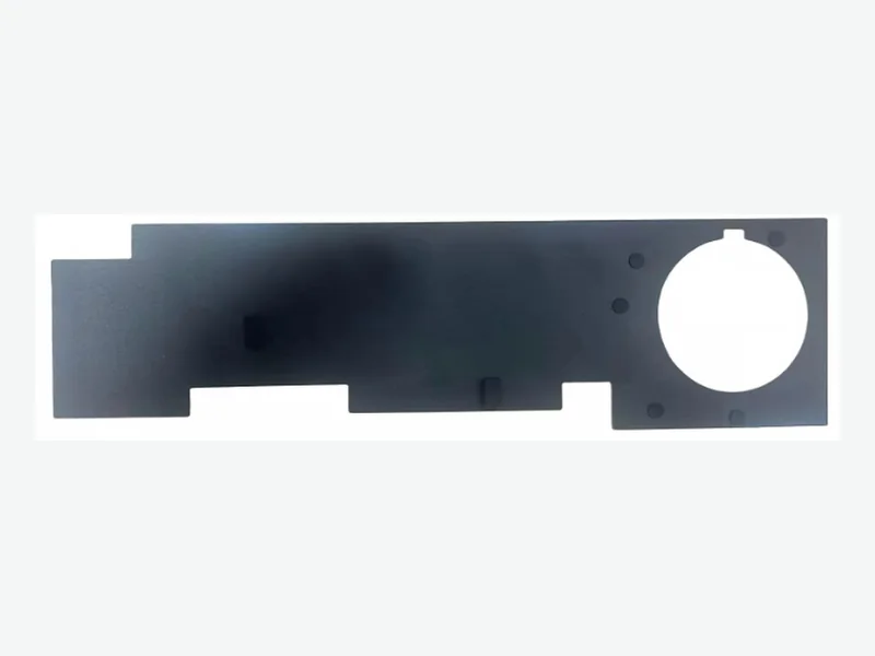
Creates thin electrical separation around PCBs, housings, busbars, batteries, terminals and power components.
We define the finished part around the selected material grade, test basis, drawing and assembly conditions. The items below can be included in the project review and data package.
How to read these values: Published ranges are representative design-screening windows across material families FLEXCEND can source, convert and evaluate. They are not one universal finished-part specification. Final values are confirmed against the exact grade, thickness, adhesive stack, test method, approved drawing, production lot and complete customer assembly.
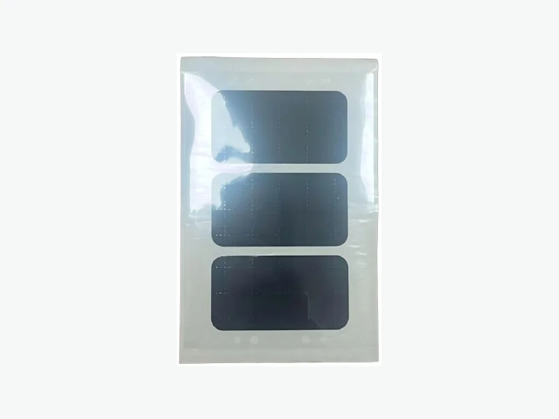
This image was extracted from the supplied product library and shows a representative part family. Exact material, grade, thickness and dimensions are defined by the approved drawing and material specification.
The exact content is agreed by program. Performance values stay linked to the selected material, thickness, method and test condition.
Approved material grade, complete layer stack, adhesive, carrier and liner recorded against the customer drawing
Supplier TDS or relevant test data tied to the selected grade, thickness, method and test condition
Critical dimensions and tolerances reviewed against material behavior, part geometry, tooling and process route
Fit samples, comparison sets and dimensional reporting can be agreed before production release
RoHS, REACH, halogen, flammability or other declarations supplied only when supported by the exact selected material
Drawing revision, material or production lot, inspection plan, liner format, kitting and packaging defined by program
We review how material, adhesive, liner, lamination, geometry and delivery format work together at assembly.
A drawing plus these operating conditions lets us recommend a practical construction instead of a generic material.
Working voltage, creepage, clearance, edge geometry and the complete assembly determine insulation performance; material data alone is not a system rating.
Integrate heat spreading, gap filling and electrical insulation around dense flight-controller electronics using die-cut parts matched to PCB layout and enclosure interfaces.
ExploreCustom lightweight spacing, cushioning, insulation and thermal-interface parts for UAV battery packs designed by the customer’s battery engineering team.
ExploreCustom thermal-interface, shielding and insulation components for compact mobile-robot controllers, power electronics and communication modules.
Explore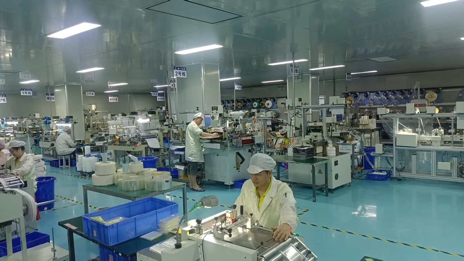
Prototype and production methods are selected around the material behavior, geometry, laminated stack and program volume.
See factory capabilitiesTell us the installation position, material challenge, environment and project stage. Our team will review the drawing and recommend a practical construction.