
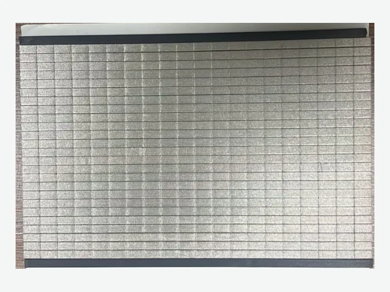
A robot controller conductive foam compression specification is a mechanical tolerance problem before it is an electrical one. The gasket must stay within its working deflection range across the full seam gap tolerance, including cover bow, fastener spacing, and temperature effects. Only after that range is fixed can contact resistance and shielding effectiveness be meaningfully compared.
Why the seam gap tolerance controls the specification
Enclosure seams are a primary leakage path for high-frequency EMI, and even small gaps can reduce shielding effectiveness significantly. A conductive foam gasket fills that gap, but its performance depends on the installed compression. If the gap varies along the seam, the gasket sees different deflection at every point, and the contact resistance will vary with it.[1]
For a robot controller, the cover is typically a formed sheet metal or machined plate fastened to a chassis. The nominal gap is set by the design, but tolerances from forming, machining, and fastener torque create a range. A specification that only states a target deflection at nominal gap will fail at the extremes. The correct approach is to define the minimum and maximum installed gap, then select a foam thickness and compression range that keeps the gasket within its working window at both limits.
- Measure or calculate the worst-case minimum and maximum seam gap, not just the nominal value.
- Include cover bow between fasteners and any thermal expansion effects.
- Select a foam thickness so that the minimum gap produces at least the minimum recommended deflection and the maximum gap does not exceed the maximum recommended deflection.
Compression set and the risk of losing contact over time
Compression set is the permanent deformation a foam retains after being compressed for a period. For conductive foam gaskets, selected constructions publish compression set values from below 5% to below 15%, depending on the core material, strain level, time, and temperature. A gasket that takes a set loses recovery force, which can increase contact resistance or open the seam electrically.[2]
In a robot controller, the gasket may be compressed for years at elevated internal temperatures. The specification should state the maximum expected temperature and the required service life, then compare candidate foams under those conditions. A foam with a low published compression set at room temperature may behave differently at 70°C or 85°C. The final selection must be validated with the actual enclosure and closure force.
- Request compression set data at the maximum operating temperature, not just ambient.
- Consider the effect of repeated cover removal and reinstallation during service.
- A lower compression set generally means better long-term contact stability, but it must be balanced against closure force.
Contact resistance versus compression: what the data means
Through resistance of a conductive foam gasket decreases as compression increases, but the relationship is not linear. A selected conductive foam reference shows less than 40 mΩ at 30% deflection under its stated test method. At lower deflection, resistance rises; at higher deflection, the improvement may be small while the closure force increases sharply.[2]
For a robot controller seam, the target should be a deflection that keeps the through resistance below the value needed for the grounding path. That value depends on the circuit impedance and the frequency of concern. A specification that simply says 'low resistance' is not testable. Instead, state the maximum acceptable through resistance at the minimum installed deflection, and require the supplier to provide data at that condition.
- Specify through resistance at the minimum installed deflection, not at a nominal 30%.
- Ask for the test method and probe area used for any published resistance value.
- Remember that contact resistance at the foam-to-metal interface can dominate the total path resistance.
Closure force and cover deflection limits
A conductive foam gasket exerts a force on the cover that depends on its compression, cross-section, and foam density. If the cover is thin or the fasteners are widely spaced, that force can bow the cover and change the gap, which in turn changes the compression. This is a coupled problem: the gasket force affects the gap, and the gap affects the gasket force.
When cover deflection is limited, the specification must include the maximum allowable closure force per unit length of seam. The foam cross-section and density can then be selected to stay within that limit while still achieving the required deflection. A thicker, softer foam may provide the same deflection with less force than a thinner, denser one, but it may also have a higher compression set.
- Calculate the maximum allowable closure force from the cover stiffness and fastener pattern.
- Request compression force-deflection data for candidate foams at the intended cross-section.
- Verify that the cover bow at maximum force does not reduce the minimum gap below the gasket's working range.
Shielding effectiveness depends on the installed condition
Published shielding effectiveness for conductive foam gaskets is typically measured in a controlled fixture with a specific compression and grounding configuration. Representative grade data shows values from above 70 dB to about 95 dB, with some profiles exceeding 100 dB under their published methods. These numbers are useful for screening, but they do not transfer directly to a robot controller enclosure.[2]
The installed shielding effectiveness is determined by the seam geometry, the gasket compression, the surface conductivity of the mating parts, and the frequency range. A gasket that shows 90 dB in a fixture may provide only 40 dB in a real enclosure if the compression is too low or the mating surfaces are not conductive. The specification should require a shielding effectiveness test on the actual enclosure, not just a material data sheet.
- Use published shielding data only for initial material screening.
- Specify a shielding effectiveness test on the assembled controller at the required frequency range.
- Include the gasket compression and surface preparation in the test procedure.
Drawing inputs that make a gasket RFQ reviewable
A conductive foam gasket drawing should define the part geometry, the foam construction, the conductive layer, any adhesive, and the liner format. For a robot controller seam, the drawing must also state the nominal gap, the gap tolerance, the target deflection range, and the maximum closure force. Without these values, the supplier cannot confirm that the gasket will work in the assembly.
The drawing should also specify the surface finish and conductivity of the mating parts, the operating temperature range, and any environmental requirements such as humidity or chemical exposure. These factors affect both the electrical contact and the long-term stability of the foam. A complete drawing package allows the converter to review the stack-up and propose a construction that meets the mechanical and electrical requirements together.
- Include nominal gap, gap tolerance, and target deflection range on the drawing.
- State the maximum allowable closure force per unit length.
- Specify the mating surface material, finish, and conductivity.
- Define the operating temperature range and any environmental exposure.
Validation protocol for a robot controller seam gasket
A practical validation sequence starts with a mechanical check of the installed compression. Measure the gap at multiple points along the seam with the cover installed and fastened to the specified torque. Confirm that the gasket deflection at every point falls within the selected working range. If it does not, adjust the foam thickness or the fastener pattern before proceeding to electrical tests.
Next, measure the DC resistance across the seam at several locations. The resistance should be stable and below the specified maximum. Then perform a shielding effectiveness test on the assembled controller over the required frequency range. Finally, run a thermal cycling or accelerated aging test to check for compression set and resistance drift. This sequence catches mechanical problems before they become EMC failures.
- Measure installed gap at multiple points with the cover fastened to specification.
- Measure DC resistance across the seam at several locations.
- Perform shielding effectiveness on the assembled controller.
- Run thermal cycling or aging to check compression set and resistance stability.
What to send for a useful review
- Seam geometry: length, width, and nominal gap of the controller enclosure seam.
- Gap tolerance: worst-case minimum and maximum installed gap including cover bow and thermal effects.
- Target deflection range: minimum and maximum compression percentage for the selected foam.
- Maximum allowable closure force per unit length of seam.
- Required shielding effectiveness and frequency range for the assembled controller.
- Maximum acceptable through resistance at the minimum installed deflection.
- Operating temperature range and any environmental exposure (humidity, chemicals).
- Mating surface material, finish, and conductivity.
- Drawing with foam construction, conductive layer, adhesive, and liner format.
- Annual volume and any packaging or labeling requirements.
Questions teams ask during selection
What is the recommended compression range for a conductive foam gasket?
Typical published windows for selected grades are 15–50% deflection. The final target depends on the enclosure gap, closure force, and required contact resistance. Operating below 15% risks high resistance; above 50% risks excessive force and compression set.[2]
How do I measure the installed compression on a robot controller seam?
Measure the gap between the cover and chassis at multiple points with the cover fastened to the specified torque. Subtract the installed gap from the free foam thickness to get the deflection, then divide by the free thickness to get the percentage. Compare this to the gasket's working range.
What contact resistance should I specify for a conductive foam gasket?
Specify the maximum acceptable through resistance at the minimum installed deflection. A selected conductive foam reference shows less than 40 mΩ at 30% deflection, but your value should be based on the grounding path requirements and the actual deflection. Request data at your specific condition.[2]
Can I use conductive fabric tape instead of foam for a robot controller seam?
Conductive fabric tape is thinner and works in limited space, but it does not accommodate large gap variations. If the seam gap is well controlled and the cover deflection is minimal, tape may be suitable. For variable gaps, foam is usually better because it maintains contact over a wider deflection range.[3]
How does temperature affect conductive foam gasket performance?
Temperature affects compression set, recovery force, and contact resistance. Selected complete conductive foam constructions operate from -40 to 125°C, but the long-term compression set at elevated temperature must be validated for your specific foam and enclosure. Request data at your maximum operating temperature.[2]
Sources and technical references
References support the published context and cited data. Final material and assembly decisions still require grade-specific documentation and application validation.
- EMI Shielded Enclosure Design Guide: Principles, Materials, and Best Practices - PCB Design & Layout - PCBwaypcbway.com · Accessed
- Conductive Foam Gaskets engineering data and screening boundariesFLEXCEND Engineering · Accessed
- Conductive Fabric Tape engineering data and screening boundariesFLEXCEND Engineering · Accessed