
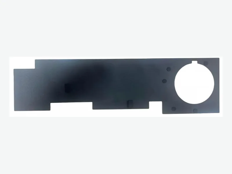
PET and polyimide are both viable die-cut insulation films for compact robot controllers, but they solve different problems. Choose PET when the controller operates below roughly 125°C, cost pressure is high, and a slightly thicker film is acceptable. Choose polyimide when the design must handle higher temperatures, tight folds, or the thinnest possible barrier without sacrificing dielectric strength.
Start with the real operating temperature, not the datasheet headline
The first decision boundary is continuous operating temperature at the insulation location. Selected PET dielectric films are published to about 125°C, while polyimide may support higher-temperature designs, but the adhesive and complete assembly set the final limit.[1]
A robot controller mounted near motor drivers or power stages can see local hot spots well above the enclosure ambient. If the insulation sits against a heatsink or a switching node, measure the actual surface temperature during worst-case load. PET is often adequate for logic boards and low-power sections, but polyimide becomes the safer default when the film must survive reflow, solder rework, or continuous exposure above PET's practical ceiling.
- Measure the insulation surface temperature, not just the enclosure air temperature.
- Check whether the film must survive solder reflow or rework cycles.
- Confirm the adhesive's continuous-use rating, not only the film's rating.
Dielectric strength is not a single number
Published dielectric strength values are always tied to a specific thickness, test method, and temperature. Selected PI grades show about 154–315 kV/mm, while selected PET dielectric grades can reach about 290–350 kV/mm under their stated tests.[1]
A thinner film does not automatically give a proportionally lower breakdown voltage because breakdown strength often increases as thickness decreases. However, the actual withstand voltage of a die-cut part depends on edge quality, burrs, adhesive squeeze-out, and any pinholes or scratches introduced during converting. Always specify the test method and accept that material-level data is a screening input, not a system rating.
- Request dielectric strength with the exact film thickness and test standard.
- Account for edge damage and adhesive flow in the final part.
- Treat published kV/mm values as screening data, not a guaranteed part rating.
Creepage, clearance, and edge coverage decide more than the film choice
Creepage is the distance along the surface of the insulation between conductors, while clearance is the shortest distance through air. Both are hard pass/fail criteria in safety testing and depend on working voltage, pollution degree, and isolation class.[2]
A die-cut insulation part can increase creepage by wrapping over a board edge or covering a connector pin, but only if the cut geometry is accurate and the adhesive holds the film in place. PET and polyimide can both be die-cut with tight tolerances, but polyimide's higher dimensional stability at temperature makes it more predictable when the part must maintain a precise edge position near a high-voltage node.
- Define creepage and clearance requirements before selecting film type.
- Use edge wrapping or folded tabs to extend creepage without adding board area.
- Verify the die-cut part's edge position after thermal cycling.
Thickness, space, and bend radius drive the practical choice
Representative PET electronics films range from 0.012 mm to 0.500 mm, while representative high-performance PI films range from 0.0127 mm to 0.125 mm.[1]
In a compact robot controller, available height is often the binding constraint. If the design can accept a 0.05 mm or 0.075 mm PET layer, the cost advantage is significant. If the insulation must fold around a tight corner or fit under a connector with almost no clearance, polyimide's thinner available gauges and better flex endurance become decisive. Always check the minimum bend radius for the chosen grade and adhesive stack.
- Compare total stack height including adhesive and liner.
- Check the minimum bend radius for folded or wrapped parts.
- Use polyimide when the available thickness is below about 0.025 mm and temperature is elevated.
Cost comparison: PET wins on price, polyimide wins on performance density
PET remains common because it offers low cost, dimensional stability, and useful dielectric strength. Polyimide film serves higher-temperature and thinner-gauge applications but typically costs several times more per square meter.[3]
The total cost difference is not only the film price. Polyimide often requires more careful handling, slower cutting, and tighter process controls, which can increase conversion cost. However, if polyimide allows a thinner part, a smaller board, or elimination of a secondary insulator, the system-level cost may favor it. Evaluate both material and conversion cost against the full assembly.
- Request quotes for both film types at the same thickness and part geometry.
- Include scrap, handling, and inspection costs in the comparison.
- Consider whether a thinner polyimide part can reduce overall enclosure size.
Decision matrix for PET vs polyimide in robot controllers
Use this matrix to shortlist the film family before requesting detailed data. The final selection still depends on the exact grade, adhesive, and validated assembly.
- Continuous temperature below 125°C and cost-sensitive: PET
- Continuous temperature above 125°C or solder reflow exposure: Polyimide
- Available thickness 0.05 mm or greater and no tight folds: PET
- Available thickness below 0.025 mm or tight bend radius: Polyimide
- High-volume, low-complexity flat parts: PET
- High-voltage nodes with tight edge position tolerance: Polyimide
Validation protocol before releasing the drawing
A practical validation sequence for a die-cut insulation part in a robot controller should include electrical, mechanical, and environmental checks. Start with a withstand voltage test on the actual part at the maximum operating temperature, not just at room temperature.
Then perform thermal cycling from the minimum storage temperature to the maximum operating temperature for at least 10 cycles, checking for delamination, edge lifting, or adhesive squeeze-out. Finally, verify creepage and clearance on the assembled board with the insulation in place, because the part's final position after assembly is what matters for safety.
- Withstand voltage test at maximum operating temperature
- Thermal cycling with visual and adhesion checks
- Creepage and clearance measurement on the assembled board
- Adhesive peel test on the actual substrate after aging
What to send for a useful review
- Maximum continuous and transient voltage at the insulation location
- Operating and peak temperature at the film surface
- Available thickness and minimum bend radius
- Required creepage and clearance distances
- Adhesive type and substrate surface finish
- Die-cut part geometry with edge and fold details
- Flammability or compliance requirements (UL 94, RoHS, REACH)
- Annual volume and target cost per part
- Drawing or 3D model of the controller assembly
- Any solder reflow or rework exposure
Questions teams ask during selection
Can PET film replace polyimide in a robot controller that sees brief temperature spikes?
Brief spikes above PET's continuous rating may be acceptable if the film's short-term thermal capability and the adhesive's peak temperature are verified. However, repeated spikes or exposure above about 125°C usually justify polyimide.
Does a higher dielectric strength number always mean a better insulation part?
No. Dielectric strength is thickness- and test-dependent. A thinner film can have a higher kV/mm value but a lower absolute withstand voltage. The part's edge quality, adhesive, and assembly position matter more for system safety.
How do I specify creepage and clearance on a die-cut insulation drawing?
Define the minimum creepage path along the film surface and the minimum clearance through air between conductors. Show the film's final position, edge wrap, and any cutouts. The drawing should reference the applicable safety standard and pollution degree.
Is polyimide always more expensive than PET for die-cut parts?
Yes, polyimide film typically costs several times more per square meter than PET, and conversion may add cost due to slower processing. However, a thinner polyimide part can reduce overall assembly size and may be cost-effective at the system level.[3]
What adhesive should I use with PET or polyimide insulation in a robot controller?
The adhesive must match the substrate, operating temperature, and any reflow exposure. Acrylic and silicone adhesives are common. Always validate peel strength and outgassing on the actual controller surface after thermal aging.
Sources and technical references
References support the published context and cited data. Final material and assembly decisions still require grade-specific documentation and application validation.
- PET & PI Insulation Parts engineering data and screening boundariesFLEXCEND Engineering · Accessed
- Why Isolated DC/DC Power Supplies Fail Late, Würth Elektronik Podcastpassive-components.eu · Published · Accessed
- 10 Leading Electronic Insulation Film Manufacturers Gainopenpr.com · Accessed